Skip to content
oapogee

Mounting

The internal sled and the external pod, static port sizing and placement, the stability check you must do, and what payload mass costs you in altitude.

draftintermediateupdated 2026-09-077 open markers

Written, not reviewed by anyone. Check the primary sources it links to.

This is where the claim that oApogee attaches to any model rocket either becomes true or does not.

Two form factors

Form A: the internal sled

A printed sled that slides into a payload bay, cut for the bore of a BT-55 body tube by default.

Use this if your rocket already has a payload section. It is the lighter and lower-drag option, it does not change the outside of the airframe at all, and it puts the payload on the vehicle centreline where its mass has the least awkward effect. Its limitation is that it only works on rockets that have somewhere to put it, and the board is now wider than a BT-50 bore, so that is the floor.

A coupler is narrower than the tube it joins, so it is not the same fit either. Measure yours and re-render with that bore rather than assuming.

Form B: the external pod

A streamlined printed fairing that straps or tapes to the outside of the body tube, in the manner of a rail button pod.

This is the one that makes the "any rocket" claim true. It requires no modification to the airframe, it works on a rocket you already own and like, and it comes off again afterwards. Nothing gets drilled, cut, or glued to a rocket you care about.

It also costs you something, and this page is the wrong place to be shy about it. A pod on the outside adds drag, adds asymmetric drag, and moves both the centre of gravity and the centre of pressure in ways that depend entirely on where you put it. On a small light rocket that is not a rounding error. "No modification to the airframe" is not the same as "no effect on the rocket."

Unverifiedmeasure the altitude penalty of the pod against the same rocket and motor flown without it, several times each, and publish both the mean and the spread. This is the number that decides whether the pod is worth it and it should come from flights rather than from simulation alone.

Printed files

Both form factors are below, as OpenSCAD source and as rendered STLs, with every dimension they are built from and where each one came from.

The pod is two parts. A single-piece pod has a cavity that opens somewhere and every choice is bad: upward leaves the payload uncovered, downward onto the tube leaves nothing holding the board, and neither prints, because the pod is convex on top and concave underneath so no orientation puts a flat face on the bed. Split at the top of the cell, both halves have a large flat face, both print it face down with no supports, and the saddle ends up facing upward where a concave surface costs nothing.

Needs hardwarethe board outline is a guess and it is the most important input to both parts. Fix it in the PCB layout, measure a fabricated board, and update data/mechanical.yaml. Until then these print as fit checks.

Static ports

A barometric sensor inside a sealed tube measures the tube. It produces a smooth, confident, entirely fictional altitude curve, which is worse than an obvious failure because nothing about it looks wrong.

Static ports are the holes that let the sensor see outside air. Getting them right is the difference between a flight profile and a fiction.

The rules

  1. More than one hole, evenly spaced around the circumference. A single hole makes the reading depend on which way that hole faces relative to the airflow. Three or four spaced evenly average out yaw and roll.
  2. Away from discontinuities. Keep them clear of the nose cone shoulder, fin roots, and any step in the airframe. Air near those places is disturbed by the airframe, and disturbed air is not ambient.
  3. Beside the sensor, not far from it. The volume the sensor shares with the ports should be small and directly connected.
  4. Deburr them. A raised lip around a drilled hole trips the airflow over it, which is exactly the thing the port exists to avoid. Take the burr off with a knife or a larger drill bit turned by hand.
  5. Check them on every flight day. Paint, glue, tape and swarf all block ports, and a blocked port is on the preflight checklist for that reason.

Sizing

Unverifiedpublish the port diameter and count, with the vent-area-to-volume rule they came from, its source, and the arithmetic for the standard sled and pod volumes. Then fly the same rocket with two port configurations and compare.

Stability, which is a safety issue

Re-simulate your rocket in OpenRocket with the payload mass and position included, before you fly it.

Not after. Not on the second flight. A rocket that has flown well ten times tells you nothing about how it flies with a payload in a new place, because the thing that makes a rocket stable is the relationship between two points that you have just moved.

A rocket is stable when its centre of pressure sits behind its centre of gravity. Adding mass moves the centre of gravity, and which way depends entirely on where the payload goes relative to the existing balance point: forward of it moves the centre of gravity forward, aft of it moves it backwards. Too far back and the rocket is unstable, which does not mean it flies badly, it means it flies sideways.

Too far forward has a cost too. A large stability margin makes the rocket weathercock hard into the wind, which loses altitude and can send it downrange over people.

The external pod makes this easier to get wrong than the sled, because the pod can be strapped anywhere along the tube and the convenient place is not always the right one.

What to aim for

Unverifiedstate the caliber margin oApogee recommends, quoted from NAR or Tripoli guidance with a citation rather than asserted from memory. This is a safety number and it does not get a rule of thumb from an anonymous website.

A worked example

Unverifieda named kit, its published margin unloaded on a specific motor, then the same rocket with a pod at two positions, one sensible and one badly chosen, with the resulting margins. Publish the OpenRocket file, not a screenshot.

Mass budget

Every gram you add is altitude you do not get. How much depends on the motor: the smaller the motor, the more a fixed payload mass costs you as a fraction.

Unverifiedpublish a table of apogee against payload mass for A, B, C, D and E motors on a representative airframe, generated from OpenRocket and checked against at least one real flight per motor class. A reader deciding between Solo and Track deserves to see what the extra mass costs them before they order.

The qualitative shape, which is safe to state without measuring: a payload that is a small fraction of the total liftoff mass costs little; one that is a significant fraction costs a lot; and on the smallest motors, a payload can be a large enough fraction that the flight is not worth doing. That last case is real and it is why Solo exists.

Why the hardware is bright yellow

The board soldermask and the printed pod are hi-vis yellow or orange. This is a recovery decision, not a styling one.

A payload that comes off the rocket, or a rocket that lands in tall grass, is found by eye. A bright object in a green or brown field is visible from many times the distance a black or white one is, and the walk to recover it is shorter and more likely to succeed. Every recovery aid on this board exists because a payload you cannot find is a payload whose data you do not have.

Print your pod in the brightest filament you own. Do not print it black because it looks better on the rocket.

Securing the payload

Two things must not move: the board, and the cell.

The board moving means joints flex under boost, and a flexing joint fails at the worst moment. The cell moving is worse: a lithium cell that shifts under acceleration and lands on a solder joint is a short circuit inside a sealed plastic box.

Route the wires so that closing the enclosure cannot pinch them. Then shake the closed assembly hard and listen. Anything you can hear moving in your hand moves far harder under boost, where the acceleration is many times what your arm can produce.

Antennas

A Link or Track payload has one antenna, a Track payload has two, and both plug into sockets rather than being soldered down. That is deliberate: where an antenna goes is a question about your airframe, not about the board, and the two antennas want opposite things.

The radio antenna wants to be away from metal and along the airframe. It is transmitting to somebody standing on the ground, so the useful direction is sideways and down, not up. A quarter-wave wire run along the inside of a body tube is the usual answer and costs nothing.

The GNSS antenna wants to see sky. It is receiving from satellites overhead, which puts it in direct conflict with the radio antenna's preferences and with most of the places a payload physically fits. A patch antenna is directional and needs to point up; a helical is less fussy and worse in the open.

Two constraints that decide more than the antenna choice does:

  • Airframe material. Cardboard and most plastics are close to transparent at both frequencies. Carbon fibre is not: it is conductive, and a payload sealed inside a carbon tube is a payload inside a Faraday cage. Metal is worse.
  • Distance from each other. A transmitter and a receiver a few centimetres apart share a small volume, and the transmitter is many orders of magnitude louder than the satellites the receiver is listening for.

Unverifieddistances rather than directions. A range test with the antenna in the positions people actually use, and a time to first fix measured inside a real airframe rather than on a bench. Both are named on the antenna rows in the bill of materials.

Fitting to the rail

Check that the rocket still slides freely on the launch rail with the pod fitted. An external pod is the most common thing to catch on a rail button or a launch lug, and discovering it at the pad with a queue behind you is a bad time to find out.
Printed parts

Parametric source, not just exported STLs, in a format that opens without a commercial licence. Change a dimension in data/mechanical.yaml, run make mech, and both the models and this page follow.

Print these to check fit, not to fly

8 of the 28 dimensions below are provisional, including the board outline, because no board has been fabricated to measure. The geometry is real and the numbers it is built from are not yet. A part printed today is a fit check.

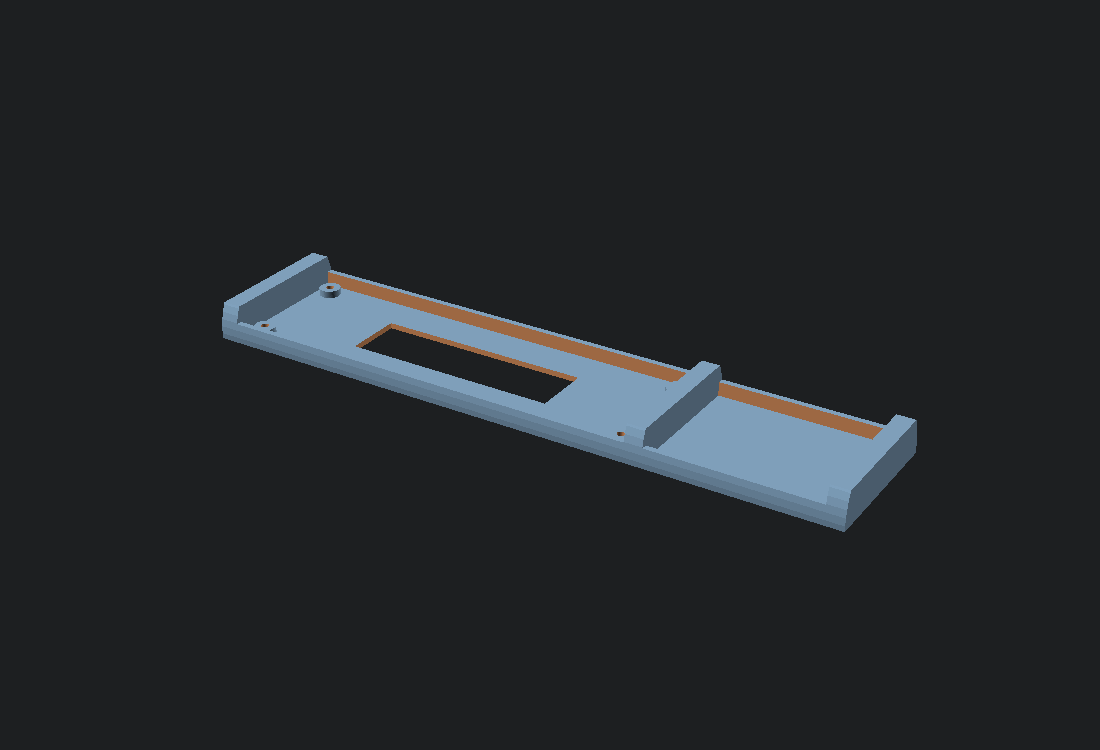
Rendered view of the oApogee pod, lower half

Pod, lower half

Carries the cell, takes the two straps, and sits on the body tube. The saddle is cut for tube_od, so a builder with a different airframe changes one number and re-renders rather than asking for a new file.

Overall: 150.8 × 31.8 × 15.9 mm

Printing: Flat split face down, no supports. That puts the saddle facing upward, where a concave surface costs nothing, and gives the first layer the largest flat face on the part.

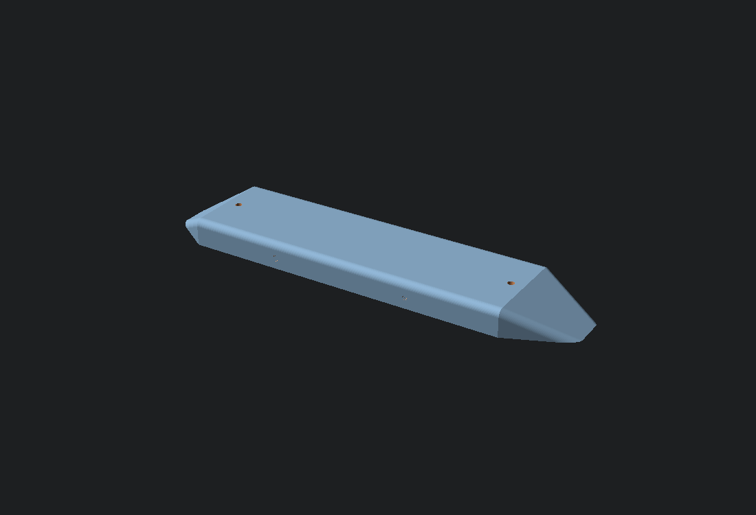
Rendered view of the oApogee pod, upper half

Pod, upper half

Covers the board and carries the static port marks. Two M2 screws into the bosses in the base; the base wall continues up inside it as a spigot so the halves locate on each other rather than on the screws.

Overall: 141.9 × 31.8 × 8.7 mm

Printing: Flat split face down, no supports. The aerodynamic surface then faces up and is never a bridge.

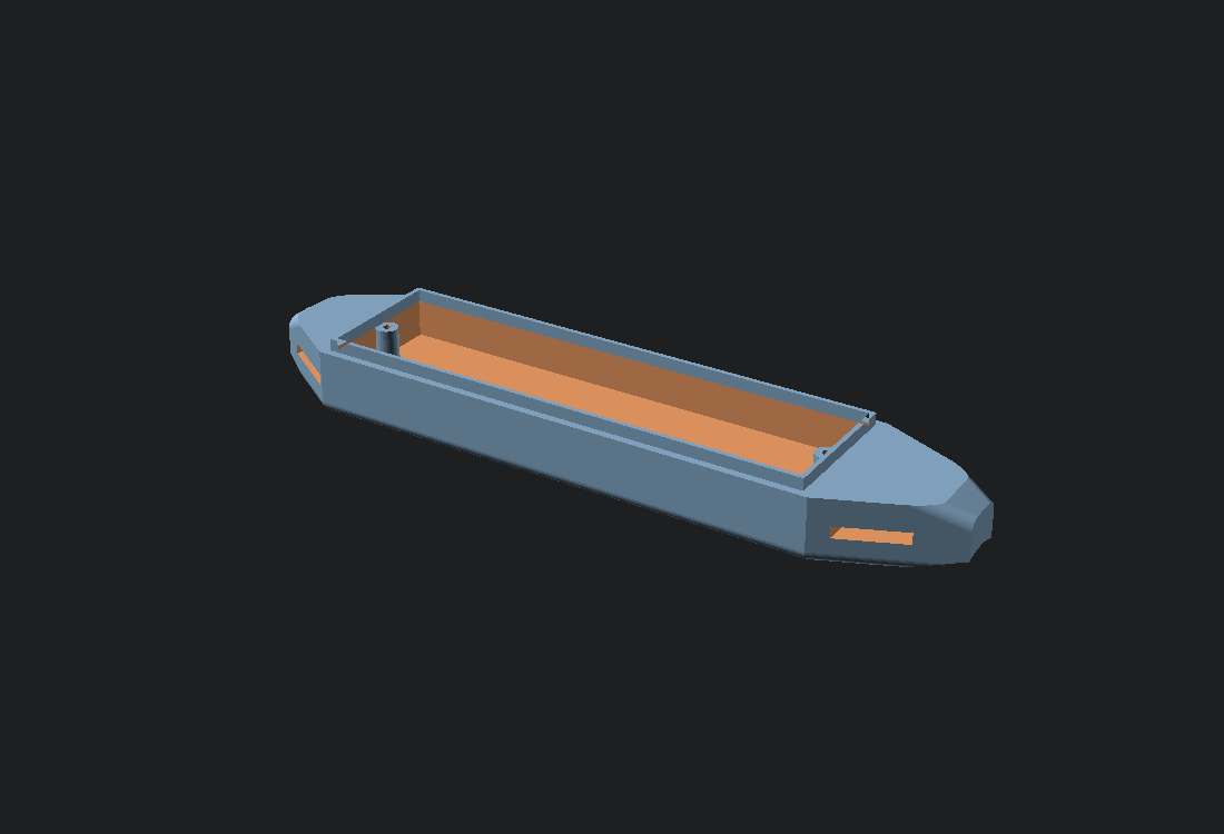
Rendered view of the oApogee internal sled

Internal sled

Slides into a payload bay or coupler. Lighter, no drag penalty, and on the centreline where the payload mass has the least awkward effect on stability. It needs a rocket with somewhere to put it.

Overall: 141.4 × 32.3 × 7.8 mm

Printing: Floor down, no supports. Print one and check it slides in your own tube before printing anything else: paper tube bore varies enough between production runs to be worth five minutes.

The pod is parametric on body tube diameter, so an unusual airframe is one number rather than a request for a new file: openscad -D tube_od=41.6 -o base.stl pod-base.scad. Measure your own tube. Paper stock varies with humidity and between production runs, and the saddle is where that variation shows up as a rock.

Every dimension, and where it came from

Generated from the same file the models are. A dimension marked provisional is not measured and not sourced, and says what would close it.

Board

The payload PCB. The outline is the routed layout's own, and make data fails if it stops matching the board element in hardware/oapogee.tsx, because the enclosure is built around it. Everything here is still provisional: a layout is not a fabricated board, and nothing has been put against a pair of calipers.

  • 92 mmLong dimension of the PCB outline.provisionalboard_length

    Needs hardware: mirrors the board element in hardware/oapogee.tsx, which is the closest thing to an outline that exists. check-data fails if the two disagree, because they did: this file said 55 by 20 while the circuit source said 60 by 22, and the enclosure was being built for a board nothing else described. Neither is measured until a board is fabricated and put on calipers.

  • 28 mmShort dimension of the PCB outline.provisionalboard_width

    Needs hardware: as board_length, mirrors hardware/oapogee.tsx. This is the dimension the sled is tightest on, and it is why the board has only ever grown in one direction. What is left for the sled rail on each side is half of (tube_id minus this width minus fit_clearance), and the rail cannot usefully be thinner than floor_thickness, which is what the printer can lay down and have hold together. Widening the board eats that allowance twice over, once on each side, while lengthening it costs nothing at all. So when the layout has needed room it has been given length, and this number moves only if the tube does.

  • 1.6 mmPCB thickness.standardboard_thickness

    The default thickness for two-layer FR-4 at every prototype fabricator, and what the board will be ordered as. This one is safe to build against.

  • 2.2 mmMounting hole diameter, M2 close clearance.standardmount_hole_dia

    ISO 273 close-fit clearance hole for an M2 screw. The sled posts are sized from this rather than the other way round.

  • 3 mmCentre of each mounting hole, in from both board edges.provisionalmount_hole_inset

    Needs hardware: set by the PCB layout once the outline and the keepouts around the USB connector and the antenna are fixed.

  • 4 mmTallest component above the board.provisionalcomp_height_top

    Needs hardware: measure the assembled board. Likely set by the USB-C receptacle or the buzzer, both of which are among the tallest parts in the bill of materials.

  • 1.5 mmTallest component below the board.provisionalcomp_height_bottom

    Needs hardware: measure the assembled board. Sets how far the board stands off the sled floor, so a wrong value here means the board does not sit flat.

Cell

The lithium pouch. Sized for the cell cavity to hold it without compression, because a pouch cell under sustained pressure is a hazard.

  • 35 mmCell cavity length.provisionalcell_length

    Unverified: the bill of materials does not name a specific cell yet, and cannot until the current draw of each tier has been measured. These dimensions are for a common 1S pouch in the 150 to 250 mAh range and will be replaced with the dimensions of the cell actually chosen.

  • 20 mmCell cavity width.provisionalcell_width

    Unverified: as cell_length, the cell is not chosen yet and cannot be until per-tier current draw has been measured.

  • 6 mmCell cavity depth.provisionalcell_thickness

    Unverified: as cell_length. Must include the protection circuit, which sits at one end of the pouch and is often thicker than the pouch itself.

  • 0.6 mmSlack added around the cell on every face.practicecell_squeeze

    A pouch cell must not be a press fit. Cells swell slightly with age and charge state, and a cavity that grips one is applying sustained pressure to a lithium pouch. Retention is the strap's job, not the cavity's.

Airframe

The rocket the payload attaches to. These are the parameters a builder changes for their own vehicle, and the reason the source is published rather than only the STLs.

  • 24.8 mmBody tube outside diameter the pod saddle is cut for.standardtube_od

    Estes BT-50, 0.976 in from the published catalogue dimension. This is the one parameter most builders will change, which is the whole reason the source is published. Measure your own tube: paper tube stock varies with humidity and between production runs, and the saddle is the surface where that variation shows up as a rock.

  • 32.59 mmBody tube inside diameter the sled is sized for.standardtube_id

    Estes BT-55, 1.283 in from the published catalogue dimension. Deliberately a different airframe from tube_od above, because the two form factors suit different rockets and pretending otherwise produced a part that did not work. When the sled was first drawn this was an argument about rail thickness: a BT-50 bore is 24.13 mm and the board was narrow enough to sit inside it with a sliver of rail on each side, printable in the sense that a slicer would emit it and nothing in the sense of a part that survives a landing. The board has grown since, and the argument is now arithmetic rather than judgement: board_width exceeds a BT-50 bore, so the board does not enter that tube at all. The pod exists so a small tube needs no payload bay; a sled needs a rocket that has one, and a rocket with a payload section is a bigger rocket. Measure your own tube and re-render either way.

Pod

The external fairing, Form B.

  • 1.6 mmFairing wall thickness.derivedpod_wall

    Four perimeters at a 0.4 mm nozzle. Chosen as a multiple of the extrusion width so the slicer produces solid wall rather than a thin gap it has to fill badly.

  • 18 mmLength of the tapered leading fairing.practicepod_nose_len

    A taper long enough to keep the flow attached, kept short because every millimetre is mass and drag on the outside of somebody's rocket. The altitude penalty this trades against is unmeasured, and the Mounting page says so.

  • 26 mmLength of the tapered trailing fairing.practicepod_tail_len

    Longer than the nose. A blunt tail separates the flow and separation costs far more drag than a blunt leading edge does.

  • 13 mmWidth of each strap slot.standardstrap_slot_width

    Clears 1/2 in hook-and-loop strap, the common size, and comfortably clears a 3.6 mm cable tie. Two slots, so the pod is held at both ends.

  • 2.4 mmHeight of each strap slot.practicestrap_slot_height

    Passes doubled hook-and-loop without forcing it.

  • 4 mmHow far the body tube sinks into the underside of the pod.practicepod_saddle_depth

    Deep enough that the pod cannot rock on the tube, shallow enough that the pod does not stand proud of it any further than it must. The saddle is cut for tube_od, so changing the tube diameter reshapes this surface.

  • 1 mmSlack between the board and the cell inside the cavity.practicepod_cavity_gap

    Keeps the board off the pouch. Foam or tape fills it on assembly.

  • 5.5 mmCavity length added at each end for the screw bosses.practicepod_boss_pad

    The cap screws into two bosses standing inside the cavity, clear of the board at both ends. This is the room they need.

  • 2.5 mmHow far the base wall continues up inside the cap.practicepod_lip_height

    A spigot, so the two halves locate on each other rather than on the two screws. Screws through an unaligned joint bend the cap instead of closing it.

  • 4Number of static port pilot marks.derivedport_count

    From the rule on the Mounting page: more than one, evenly spaced, to average out yaw and roll. Four is the count that page recommends. The diameter is deliberately not published here, and the pod prints dimples rather than holes for that reason.

Sled

The internal carrier, Form A.

  • 3 mmHeight of the side rails that locate the sled in the tube.practicesled_rail_height

    Enough to keep the sled from rotating in the tube without turning it into a piston that has to be forced in.

  • 4 mmHeight of the end stops that keep the board from sliding out.practicesled_end_stop

Printing

Tuned for the machine, not for the design. Every one of these is worth changing if your first fit-check is tight or loose.

  • 0.3 mmGap added to every sliding or mating surface.practicefit_clearance

    A starting point for FDM, not a specification. If your first fit-check is tight, raise it; a well-tuned machine may want less. This is the number to change before blaming the model.

  • 0.4 mmNozzle diameter the wall thicknesses are multiples of.practicenozzle
  • 1.2 mmSolid floor under the board and the cell.derivedfloor_thickness

    Three layers at 0.4 mm. Enough to be stiff without adding mass.